
RV Hatch Motor Home Magzine

Hatchlift baggage-door gas props take the frustration and headache out of exterior compartment access by Bill and Jenn Gehr photos by Jenn Gehr
Access to the myriad miscellaneous items and whatnots that are in storage just behind those tempera- mental exterior compartments has been a major contributing factor to countless headaches — both metaphorical and physical. And unfortunately, the last 20 years have brought few advances to these standard exterior compartment door hard- ware, until now. A new retrofitted door-lift system, called Hatchlift, helps to keep those compartment doors in place when accessing storage.
Our fifth-wheel trailer has a bedroom slide that had prevented the use of a bag- gage door catch, because the slide would not allow the compartment door to fully open. Years ago, we tried to fix the problem with a bit of creative engineering and a thin piece of stainless-steel safety wire. Granted, our little invention was effective at times, but as soon as the wind was any- thing more than a slight breeze, I would end up with a bump on my skull and a few choice words that would only get me in trouble. It was time to install a fail-proof system to keep those doors in place, and Hatchlift was the perfect solution.

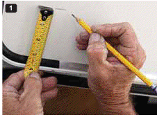
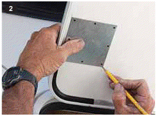
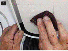
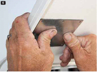
1) Measure 4 inches from the top edge of the door for the leading edge of the mounting plate. 2) With the mounting plate held into position, pencil a line around the outside edge. 3) Using the scuff pad, rough up the outlined area for the first step of
|
The simple design of the Hatchlift in- cludes a gas prop (spring assembly), two brackets, a black nylon pull strap for tall doors, screws and a specialized mounting plate. Most baggage doors are made with a foam center with little or no wood to attach any type of a brack- et with screws. Hatchlift’s pre-drilled, square-mounting plate completely solves this problem. |
in place at the recommended 130-170 degrees so that reference markings can be made 6 inches from the top and 2 inches from the edge on the inside face of the door. Once that’s done, the spring assembly with the upper and lower brackets in place is held in position to make sure it will clear any obstructions. If it doesn’t, the gas prop can be in- stalled on the opposite side of the door. Once clearance has been established, the bottom bracket is installed on the wall (or door jamb, if necessary) using the supplied screws. |
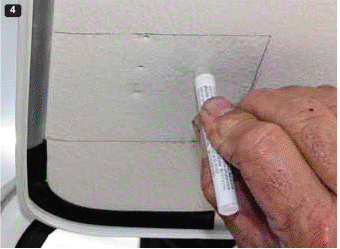
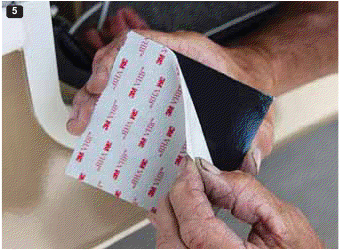
the mounting plate is attached to the face of the door, 4 inches from the top, which should cover your reference marks. I recommend that you hold the gas prop assembly in place once again to be certain it has complete clearance, top and bottom. Using the supplied pad, scuff the area where the plate is to be mounted, then clean it with rubbing al- cohol and allow it to dry. The next step is to crush the tube of primer at the small black dot and apply the entire contents to the location of the scuffed, prepped area. It takes about 10 minutes for the primer to completely dry. |

|
|
|||||||
|
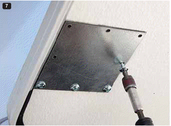
8) Install the upper bracket centered 6 inches from the top of the door. 9) Remove and install the shock stud into one of four adjustment holes. 10) Install the lower bracket at the predetermined position using the supplied self-tapping screws. 11) Remove the center screw from one of the baggage door locks and install the pull stap with the supplied screw. |
||||||||


